Cart 0

Introduction
Kistler combustion pressure sensors are precision measurement devices designed to cope with the high temperatures and thermal shock experienced in the hostile environment of diesel and gas engine cylinder monitoring. This application note discusses how to help protect the investment you have made in your sensors by taking steps to minimise possible damage due to elevated temperatures.
The maximum temperature as seen at the sensor head should not exceed 350°C. If a sensor is exposed to temperatures above this for prolonged periods, irreversible damage to the sensor can occur, and this will invalidate your warranty. Additionally, the cable connection to the sensor head should not exceed 200°C. So how do we go about ensuring that exposure to excessive temperature is avoided.
First, let’s take a look at what can cause temperatures as seen by the sensors to be elevated. Here are some guidelines:
- Four‐stroke versus two‐stroke: four‐stroke engines tend to produce higher temperatures at the sensor face than two‐stroke engines. These temperatures can be inflated by the SOLAS regulation requiring that hot cylinder heads have to be covered.
- A long gas passage between the cylinder head and the sensor can significantly increase the temperature seen at the sensor. This passage can be an extension pipe or a long passage in the indicator valve itself. The natural instinct is to assume that the further the sensor is away from the cylinder, the cooler it will be. In fact, the opposite is true. What happens is the static gas in the passage is continually being compressed and this addition of energy results in a rise in temperature. The gas passage in the water‐cooled section of the cylinder head in fact cools the gas so you should aim to have the sensor positioned as close to the cylinder head as possible. Avoid having long pipework between the cylinder head and the sensor as the temperature of the gas in this section will be increased.
- Operators have measured temperature using an infra‐red thermometer on the surface of the indicator valve to check that the temperature rating of a sensor is not being exceeded. This will measure consistently and considerably lower than the temperature that the sensor is seeing, and so is not a reliable method of temperature measurement.
Let’s take a closer look at portable and on‐line sensor installations.
Portable Sensors
By portable sensors, we mean a type that is mounted in a Thomson Adapter and moved from cylinder to cylinder, typically used with an instrument such as the DK‐20 from Icon Research. Attention should be paid to the four points below to avoid excessive temperature.
Recommended Type of Thomson Adapter
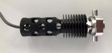
Use a Thomson Adapter with good thermal conduction characteristics. The adapter from Kistler pictured here has been shown to reduce the heat at the sensor head significantly.
Recommended Type of Indicator Valve
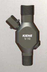
Ensure that indicator valves with short stems are fitted to the engine. The picture here shows the type of indicator valve that would be a good choice as the length of the gas passage between the cylinder head and the Thomson Adapter thread is minimised.
Issues with Long Gas Passages
As mentioned earlier, long stems (and therefore long gas passages) build up extremes of heat at the sensor. Experiments have shown that temperatures in excess of 400°C can be experienced with stems as short as 30cm or less. Pictured alongside is an indicator valve that will lead to high temperatures at the sensor head.
Measurement Time
As a precaution, don’t leave the sensor on the indicator valve for longer than necessary, or alternatively close the valve. A typical measurement using a portable instrument should not take more than one minute.
On‐Line Sensors
On‐line sensors are fitted permanently to the cylinder and so other precautions are required.
Types of Valve
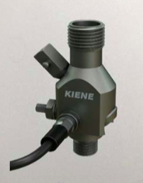
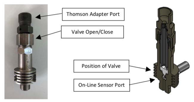
Avoid permanently connecting an on‐line sensor to the Thomson Adapter port. This type of connection means that the gas passage will be longer than it needs to be. If possible, use a dual‐port valve where the on‐line sensor fits onto its own port towards the base of the valve assembly. The example alongside shows a type of valve where the gas passage is short and the sensor will be positioned close to the cylinder head for additional cooling. Note that the passage should not be so narrow as to cause build‐up of soot.
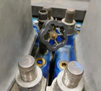
The picture below shows a valve developed together with Kiene Diesel. The valve seat is actually positioned just above the port that the on‐line sensor fits into, so the gas passage is as small as it can be. The valve is opened and closed from above by turning the hex nut allowing a temporary measurement to be taken using a sensor mounted in a Thomson Adapter.
The sensor in this arrangement will not normally need any cleaning. The normal procedure where the valves are opened and the engine turned with starting air before start‐up should be sufficient to clear away any build‐up of soot.
Open or Leaking Indicator Valves
Never run the engine with the indicator valve blowing out to open air. Tests have shown that the on‐line sensor will see a very rapid rise in temperature, as high as 50°C for each cycle, so the sensor can be overheated in a very small number of cycles. For the same reason, avoid running the engine with a leaking indicator valve as this can overheat the on‐line sensor also.
Measurement with Temporary Sensor
If a sensor is mounted temporarily on the Thomson Adapter port on the indicator valve for a reference measurement, open the valve for as short a time as possible and maximum one minute to avoid overheating the fitted on‐line sensor.
-
Further Explanation of Gas Pumping Action
For a more in‐depth explanation of temperature profiles along the gas passage, the section below gives some further details of the gas pumping action and its effect on gas temperature.
The diagrams below illustrate how ‘cold’ gas in the gas passage (as in the upper diagram) is compressed by the combustion to 1/140th of its volume when the combustion pressure is 140 bar (as in the lower diagram).
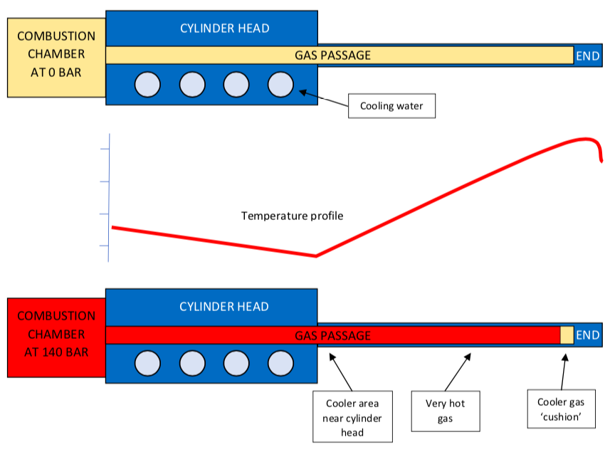
By placing a sensor close to the cylinder head, it benefits from the cooling effect of the cooling jacket. Typically, the temperature of the cylinder head will be around 120°C. However, the pumping action significantly increases the temperature of the gas at a distance from the cylinder head as shown in the temperature profile. At the very end of the gas passage, there is a very small volume of cold air remaining and the temperature at this point can be significantly lower than the gas in the main passage. But remember that this volume is very small and careful positioning of the sensor is required. To re‐iterate the earlier analysis, a short gas passage with the sensor near the cylinder head is the optimal solution.
-
Pressure Oscillations
One final point to note is that long passages are more susceptible to apparent resonance of the gas as it is pressurised dynamically. This phenomenon manifests itself as visible oscillations on the pressure signal around the firing point. Gas passages with varying diameters and split passages can lead to strangely shaped resonances. There will always be pipe oscillation in any installation but shorter gas passages will result in lower amplitude and higher frequency oscillations, the higher frequency meaning that the oscillations are more likely to be filtered out by the sensor and measuring electronics. The frequency depends on the pipe diameter and length ‐ the longer the pipe, the lower the oscillation frequency. A rule of thumb is that if the pipe diameter is equal to the gas passage length, then the oscillation frequency is approximately 13 kHz. This is another reason why shorter gas passages are more favourable.
For further information, or information on the range of Kistler pressure sensors, contact
With special thanks to Erik Nielsen of Kistler Instruments AG for his valuable input to this application note.
Issue A: April 2020